
Introduction
Since their first mass-scale use in assembling various products in Industrial Revolution of the early 19th Century, threaded bolts (or fasteners) and nuts are found on every construction site, helping to connect two or more similar or different materials. The simplest mechanism by which bolted connections work is clamping together two materials, steel for instance, thereby creating a frictional connection. Illustrated by Figure 1 below, this clamping force must generate enough resistance to tension loads and create enough friction through clamping to resist any applied shear loads. Typically, however, this clamping force cannot be measured during assembly and instead we measure the tightening torque of the nut or screw. If the clamping force is inadequate because of insufficient applied torque (under-torqueing), then the external tensile load will cause the connection to become unsafe. Conversely, too much torque (over-torqueing) can shear off the bolt. Consequently, a “Goldilocks” range for tightening torque allows the bolt / fastener to stretch properly and behave like a solid spring that clamps two materials together.

Parameters influencing Tightening Torque
Unfortunately, applying a pre-defined – or Tightening / Installation – torque to bolted connections is not enough to induce the required clamping and pre-tension force. The Tightening torque is the sum of the pre-tension and certain influencing parameters, which chiefly include overcoming the frictional losses. The image below shows a sample breakdown of the three different components of tightening torque, namely:
1. Torque required to stretch the bolt and induce the pre-tension;
2. Torque required to overcome friction between the threads of the bolt and nut; and
3. Torque required to overcome friction at the contact surface under the nut.

Beyond frictional losses, there are other factors at play and the image below captures them all.

For instance, as the graph below shows, the required clamping force / pre-tension for the bolt to achieve the same setting increases by 20Nm if the diameter also increases from M12 to M16.

Another example through the table below illustrates a baseline of 10.9 Grade M10 screw with 100mm of clamping length joining two steel materials, which illustrates the change in pre-tension that can be expected if other parameters were to change.

Failure Mechanisms & Tightening Torque for Post-installed Fasteners
For post-installed fasteners, tightening torque is equally vital and connections using such fasteners require torque to develop pre-tension in the connection as they undergo a “positive” (i.e., “tensile”) displacement that is balanced by a “negative” (i.e., “compressive”) displacement in the concrete. As a result, the amount of pre-tension, clamping, and displacement depend on the parameters noted in the previous section. While the applied torque adds some tension load on to the fastener, applying an external tensile force onto the fixture reduces the clamping force between the concrete and the fixture. Here, the stiffness of concrete will influence the relationship: since concrete typically has higher compressive stiffness when compared to a fastener’s tensile stiffness, the external (applied) tensile load minimises any residual tensile load on the fastener and this is only true as long as some clamping load remains.
While tightening torque influences the installation of all post-installed fasteners, a particular class of fasteners is particularly susceptible to the torque applied during installation: “torque-controlled” expansion fasteners, which use friction as their primary working principle (for a full overview on the working principles of post-installed fasteners, refer to this dedicated article). As a reminder, undercut and chemical fasteners still need to be torqued and this is to ensure that the baseplate is clamped firmly to the substrate.
Illustrated by the image below, the applying torque to these “torque-controlled” expansion fasteners creates an outwards pull to the fastener’s tapered cone at bottom end of a pre-drilled hole and this causes the fastener’s sleeves to expand outwards, thereby generating a friction interlock between the sleeves and the borehole in which the fastener is installed. This develops pre-tension in the fastener and a compressive clamping force between the fixture and the concrete. If the tightening torque is insufficient, then these sleeves will not expand properly and may cause a premature failure; conversely, applying too great a torque value can shear off the shank of the bolt. In the “Goldilocks” zone, there will be an equilibrium achieved between the clamping force because of correctly applied installation torque and an externally applied tensile load.

From the earlier section, it is clear that tightening torque for each fastener will be different. Subsequently, certain factors also will influence the loss of clamping force (pre-tension):
- Concrete Strength: most fasteners are developed for concrete with cylinder strengths ranging between 20 and 50 MPa. Fasteners set in concrete with higher strength may require a higher tightening torque to expand the sleeve.
- Over-torqueing: If the bolt can sufficiently accommodate a higher pre-tension, the clamping force induced by larger-than-necessary tightening torque has another consequence – it can induce splitting in the concrete (generation of cracks) and potentially spalling if close to a free edge.
- Cracks: Ever-present in concrete, cracks propagating through the fastener’s location are likely to develop during the service life of the fixing or will be present at the time of installation. These cracks will cause all fasteners to lose their pre-tension, since the displacement required by the fastener increases to bridge the gap caused by the crack. Torque-controlled expansion fasteners, in particular, respond to cracked concrete conditions extremely well as their sleeves expand to accommodate the crack, but they too lose any residual pre-tension. On the other hand, undercut, displacement-controlled expansion, and screw fasteners are affected to a greater extent and any pre-tension introduced by tightening torque reduces significantly.
- Loss of pre-tension: Until such cracks develop, however, the time elapsed after applying the tightening torque is crucial and it is quite common to see almost a 50-60% drop of the original pre-tension within the first few days. This is caused by creep and relaxation of the installation within the interface of the nut and bolt threads as well as between the stressed concrete in areas adjacent to the expansion sleeves. This is especially true for large diameter fasteners that require a large tightening torque. Re-torqueing the fastener will alleviate this loss of pre-tension to an extent.
- Fastener’s installation angle: Fastener installations deviating beyond a specific tolerance are more cumbersome not only to install, but also do not generate the requisite pre-tension to clamp the baseplate to the concrete.
Establishing the right Tightening Torque
At this point, the reader may pause to question: “From which document can I establish the tightening torque for fastener X?” Thanks to the existence of stringent qualification methods such as the European Assessment Documents – abbreviated to EAD – 330232 (mechanical) & 330499 (chemical) and ACI 355.2 (mechanical) & 355.4 (chemical), the installation torque for a specific fastener and its specific diameter is evaluated by a series of tests that includes the impact of the various factors covered by the previous section. The resulting European Technical Assessment (if assessed to the EAD) & Evaluation Report (if assessed to ACI) hold the numerical value of the required installation torque.
Highlights of the qualification methods include, among other parameters:
- Test provisions for under- and over-torqueing;
- Testing in low- (20 MPa cylinder) and high-strength concrete (50 MPa cylinder);
- Allowance for deviations in fastener installations of up to 6° (in Section 5.2.2 of ACI 355.2) or 5° (in Section 3.1.5 of TR 048 referenced by EAD 330232) perpendicular to the surface; and
- Simulate the loss of clamping force (pre-tension) over the service life of the fastener.
Most crucially, however, the tests determine the minimum distance the fastener can be positioned from the edge of the substrate (concrete or masonry) and the minimum spacing between two fasteners. It is key to follow these values during the design and installation phases as they may cause the concrete to crack / split early in its service life and, ultimately, lead to spalling. In that sense, manufacturers must compromise between tightening torque – which must be sufficiently high to guard against displacement and fatigue – and minimum spacing & edge distances – which must be practically low to allow for feasible connections.
Impact on Design and Specifications
The values for tightening torque printed in the fastener assessment reports will not alter with static, seismic, fire, or fatigue design and the Engineer simply needs to follow the minimum spacing and edge distance values in the assessment report (ETAs & ESRs) while designing a fastening, as these derive from the fastener’s installation torque. If the fastener is installed and torqued to the correct value per the ETA or ESR, the Engineer can rest assured that the fastener will perform as it was designed at Ultimate and Serviceability Levels.
However, design and installation are linked inextricably and the way fasteners are installed massively impacts both the resistance and reliability of fastenings. In the face of poor installation, all design is rendered meaningless, compromising the stability of the entire fixing and possibility even the entire structure. Along with fasteners installed greater than 5-6° from the perpendicular, under- and uneven-torqueing of single fasteners or a group may cause the design loads on the individual fasteners within the group to exceed calculated capacities, besides developing an uneven clamping force between the concrete and the fixture. As a response, it is common to see designers add multiple safety factors to compensate for improper execution at site.
Serviceability considerations for post-installed fasteners stipulate the maintaining of contact between the fixture and the substrate at service load levels. This is only possible if the applied tightening torque directly translates into a clamping force in the fastening and not on to the fastener’s sleeve. Under-torqueing means insufficient clamping force that can separate the fixture from the substrate – i.e., “lift-off”. This not only produces displacement that could exceed serviceability requirements, but also introduces a bending moment on the fastener because of shear acting on a lever arm. This results in a greater tension demand placed on the steel component of the fastening, which originally may not have been considered in the design phase. This is shown by the following figure.

The impact on design is illustrated with an example of a single M12 HST3 fastener in C25/30 concrete loaded by 25kN of shear. With applying correct torque, the fixture is in direct contact with the concrete and the fastener’s shear capacity is 27.2kN, which translates into a utilisation ratio of 92%, within the safe margin. Now assuming a similar scenario but with the fastener under-torqued, the potential 5mm lever arm decreases the fastener’s shear capacity to 6.72 kN, meaning that the fastener will be overloaded and fail.
Over-torqueing, on the other hand, also poses its own set of problems and while it is extremely tempting to apply a higher tightening torque that increases the pre-tension in the fastener and allows higher tensile resistance in the fastener, this is only possible if the minimum spacing and edge distances are increased in a linear proportion to the torque until the maximum achievable tightening torque that is dictated by the steel yield. An example with the M24 HST3 fastener below illustrates a potential scenario where the fastener is over-torqued. Note that direct contact between the washer and the baseplate, as well as the baseplate and the concrete substrate, is a pre-requisite.
a) Maximum achievable tightening torque?
- Stressed Cross-sectional area of the M24 HST3, A_s=353〖mm〗^2
- Maximum pre-tension, F_(S.V)=A_s∙f_(yk,thread)/γ_Ms =353∙450/1.41=108.6kN
- Maximum allowable Tightening Torquei^i to produce this pre-tension,
- M24 HST3 minimum edge distance, cmin = 125mm
- M24 HST3 minimum spacing, smin = 125mm
- M24 HST3 tightening torque, Tinst = 300 Nm
- New minimum spacing (smin) & edge distances (cmin) with the maximum allowable tightening torque = 125×391/300=163mm

Ultimately, the impact tightening torque plays on fastenings is significant, yet it is not complex if the fastener is assessed to either the EAD or ACI qualification criteria. The Engineer needs only to design the fastening with a proper design standard and specify the installation instructions considered in the design to the Contractor or Installer. This is possible via specifications, which translate the Engineer’s design intent into installation at site.
The Hilti Advantage – “Install as Designed”
For the project delivery team, the holy grail is ensuring the project is delivered according to the specifications laid out in the drawings and constructed on time, within budget, and avoiding any safety risks. In the journey to achieve this, it can be quite cumbersome and time-consuming to ensure the quality of installation for post-installed fixings. An avoidable inconvenience, onsite pull-out tests can be reduced if installation reliability increases with the inclusion of quality control and risk mitigation measures.
These measures centre on firstly following the manufacturer’s recommended installation instructions by using:
- Using an ETA or ESR-assessed fastener designed to a proper standard such as EN 1992-4 or ACI 318-19 Chapter 17;
- The right drilling tool and drill bit - allows faster drilling & cleaning of debris in the borehole;
- A drill-aid / -guide - guarantees installation of the fastener perpendicular to the substrate;
- [Only for bonded fasteners] Injecting the mortar with a “piston plug” - negates any potential air voids;
- A calibrated torque wrench - ensures the fastener is correctly torqued (often not found on the site)
Hilti proposes innovative solutions for Steps 1, 2, and 5 to reduce the installation time of mechanical fasteners such as HSL4 and HST3 while maintaining the desirable installation quality:
- HSL3-B & HSL4-B - contains a sacrificial “red cap” that shears off when applying the right tightening torque
- Hilti TE-CD & TE-YD hollow drill bits - drills & cleans the borehole at the same time;
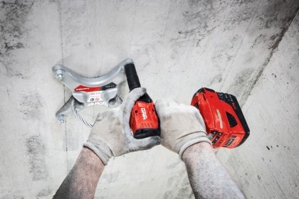
- SIW-6AT - Impact driver with an attachable “automatic torque (AT) module” that scans the bar code on box of Hilti HST3 fasteners, displays a green light once the right torque is achieved, and records all installations for documentation purposes.
